


DC 9V SMT Soldering Test Kit Electronic Practice Set
28

 Direct purchase from the factory
Ka sɛn sɔgɔsɔgɔninjɛ

 Sɔnni hɔrɔn
 Ka taa cogo
 Ka segin cogo
Sɔnni Hɔrɔn
I ni ce Roymall, i ka sɔnniw siti. An bɛ i ka dɛmɛ fɛɛrɛ. O sɔnni hɔrɔn bɛ kɛ i ka sɔnni kɛnɛ kan.Ka Taa Cogo
An bɛ sɔnniw taa i ka so la 2 don kɔnɔ. Kɛnɛ cɛsiri bɛ se ka kɛ 5-7 don kɔnɔ.1. Ka Segin Cogo
Sɔnniw bɛ segin 40 don kɔnɔ. Sɔnni yɛlɛman tɛ segin.2.Ka Sɛn Segin
I bɛ sɛn sɔrɔ segin kɔnɔ.
{"code":"00","result":"
Description:
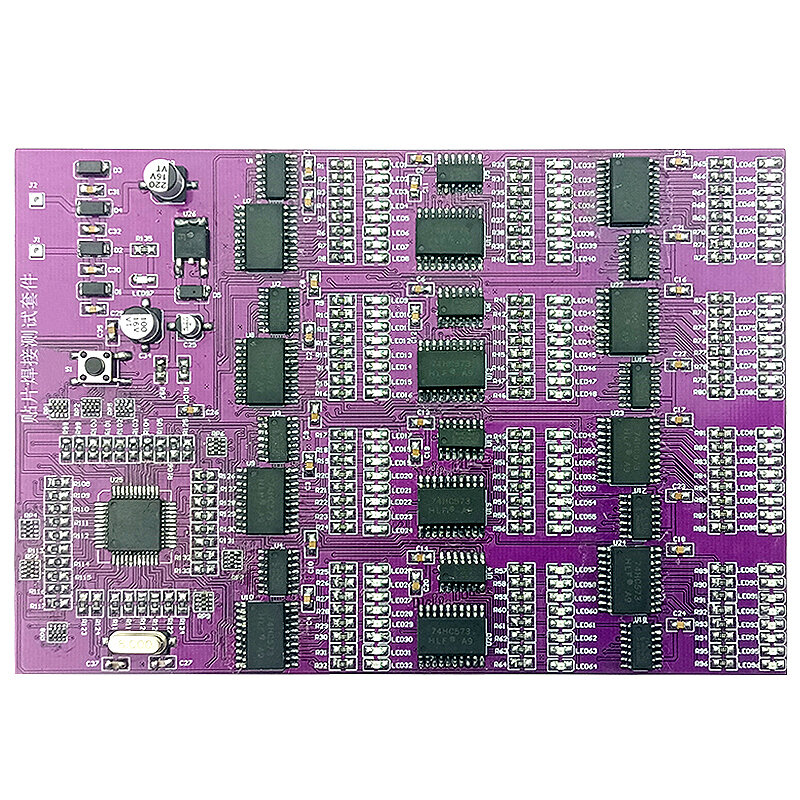
1. J1 and J2 are the power supply input terminals of the entire SMT board. It can work normally when connected to AC6V or DC9V. When working normally, all LED lights in this kit can work normally. At first, each group of LEDs flashes with water, and then flashes at intervals, and finally all Light up all the LEDs, then flash again, and cycle like this to check whether the LEDs are working and whether they are soldered well. If it is found that the corresponding LED does not flicker, it means that there is a welding error or a false welding.n
2. The AC6V power supply is rectified by D1-D4 diodes, and then through each filter capacitor to pin 1 of the voltage regulator chip 78M05 (LED97 is always on, the rectifier circuit is working normally), and the output of DC5V is supplied to the whole test circuit through pin 3.n
3. This test circuit is controlled by a single-chip microcomputer to work with 12 groups of 8-bit LED lights. Each group is composed of 1 74HC573 and 74HC164. One group can control 8 LEDs, 12 groups in total. Figure 1 is the control schematic diagram of one group. When working normally, all LED lights are on and can flash.
Specifications:
Product Name: SMD Soldering Test Kit
PCB material: FR-4PCB board
PCB size: 145*100MM
patch tape connection test
Power supply mode: DC DC9V
Applicable objects: junior welding patch personnel
Component Description: Common patch components are used
- Dɔnniya
- Anw ka ko
- Baarakɛla sɔnni
- Sɛbɛn sɛgɛn
- Baarakɛ
- Baara ɲɛnabɔ
- Tɛrɛtɛrɛli
- Baara sabaɲini
- Dɛmɛ
- Sɔn sɔrɔli
- Fɛɛrɛ
- Sɔnni Dɔnbaga
Sɔrɔ mara kura ani 15% yɛrɛma i ka sɔnni kɛnɛ kan
Wari sugandi

Kan sugandi
Tɛrɛw: