


T3231 110V-220V 12V/24V Digital Time Delay Relay LED Cycle Timer Control Switch Adjustable Timing Relay Time Delay Switch

 Direct purchase from the factory
Ka sɛn sɔgɔsɔgɔninjɛ

 Sɔnni hɔrɔn
 Ka taa cogo
 Ka segin cogo
Sɔnni Hɔrɔn
I ni ce Roymall, i ka sɔnniw siti. An bɛ i ka dɛmɛ fɛɛrɛ. O sɔnni hɔrɔn bɛ kɛ i ka sɔnni kɛnɛ kan.Ka Taa Cogo
An bɛ sɔnniw taa i ka so la 2 don kɔnɔ. Kɛnɛ cɛsiri bɛ se ka kɛ 5-7 don kɔnɔ.1. Ka Segin Cogo
Sɔnniw bɛ segin 40 don kɔnɔ. Sɔnni yɛlɛman tɛ segin.2.Ka Sɛn Segin
I bɛ sɛn sɔrɔ segin kɔnɔ.Specification:
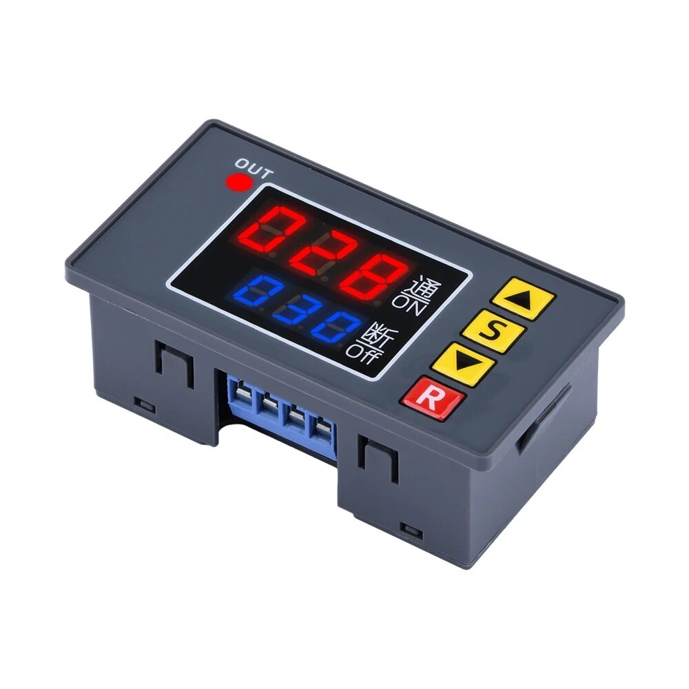
Name: Digital display time relay module
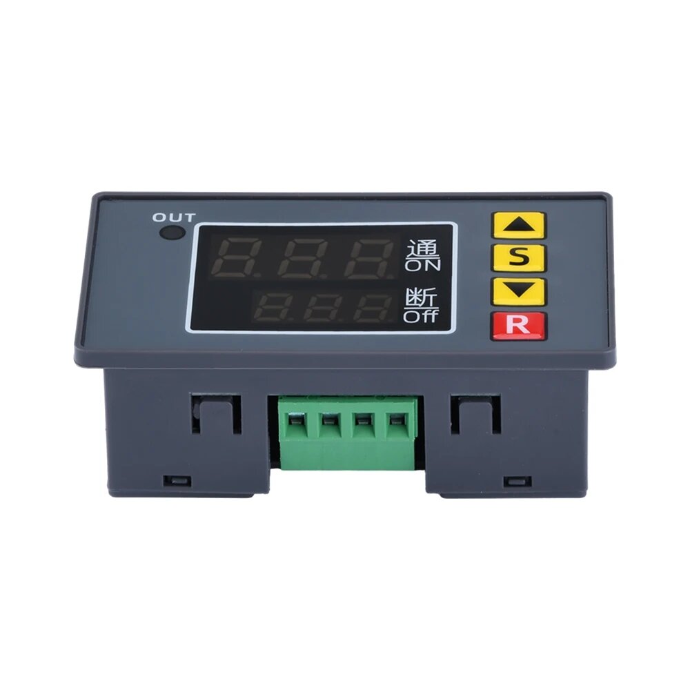
Material: plastic+metal
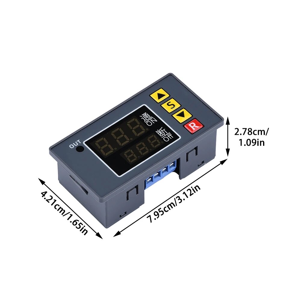
Size:
Display panel: 79mm * 43mm
Installation: 71mm * 40mm * 24mm
Color: Black
Timing range: 0-999S/0-999M/0-999H
Function: timer / delay / cycle / covering 18 kinds of functions
Maximum operating current: 10A
Type:
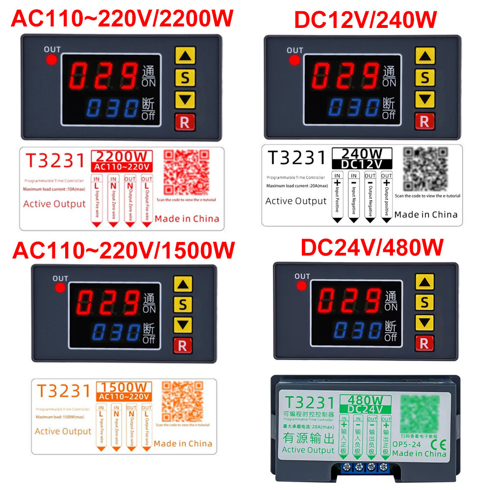
DC12V/240W, DC24V/480W, AC110~220V/1500W, AC110~220V/2200W (optional)
Function:
Can be used for timing, delay, cycle timing, intermittent timing and other occasions.
Instruction Manual:
* Before using the first prompt the user to note that after setting the data must wait 6s, 6s after the module will automatically save the memory settings data.
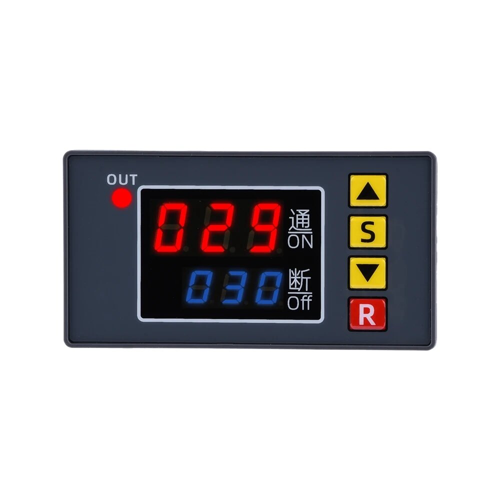
* Press the SET key once to enter the time setting mode, the red digital tube flicker, through button plus or minus button to adjust the setting time T1.After T1 is set short press the SET button again , the digital tube flicker, through button plus or minus button to set time.After time T2, T2 time is set, press the SET button again, the system will automatically save the memory setting time or wait 6s, must wait 6s,6s after the module will automatically remember to save the data.
* Long press SET to enter parameter setting mode. There are two sets of parameters for the user to select P0, P1. Pressing SET in the current mode switches P0, P1. In the P0 parameter can be set by button plus or minus button for their own timing mode. Under the P1 parameter, you can set the operation mode by pressing the button plus or minus button.
P0--0: T1 Timer time mode is seconds
P0-1: T1 timer time mode is minutes
P0--2: T1 timing time mode is hour
P1--0: T1 time delay relay (T1 timer)
P1--1: T1 delay time relay releases (T1 timer)
P1--2: time delay relay after T1 (T1 timer), then the delay time T2 successor electrical release (T2 timing) ends.
P1--3: T1 delay time relay releases (T1 timer), then the delay time T2 successor Electric energized (T2 timing) ends.
P1--4: time delay relay after T1 (T1 timer), then the delay time T2 successor electrical release (T2 timer), repeat the cycle.
P1--5: T1 delay time relay releases (T1 timer), then the delay time T2 successor Electric energized (T2 timer), repeat the cycle.
For example: A customer needs time 10 seconds to boot, 20 seconds off, would always loop. Set up as follows:
T1 set the time 10, T2 set the time 20
P0-0 (T1 timing range is seconds)
P1 - 5 (timer mode is the first to work then stop would always loop.)
Package included:
1 x Timing Delay Relay Module


